The following sections deal with strain using matrices. This section is not covered in the current version of EAS 421 but is provided here for those who are interested (especially those who have taken Math 120 and want to see how elegantly linear algebra can be used to describe strain)
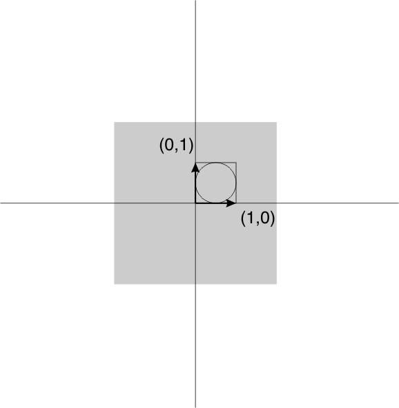
So far we have met two methods for representation of finite strain in 2D. These are the Mohr circle and the strain ellipse. We now introduce a third representation, that is actually the basis for all the theory of the strain ellipse and the Mohr circle. This is a 2 x 2 matrix of 4 numbers known as the deformation gradient tensor, or more simply as the deformation matrix and commonly represented with a bold F.
We define matrix multiplication as follows:
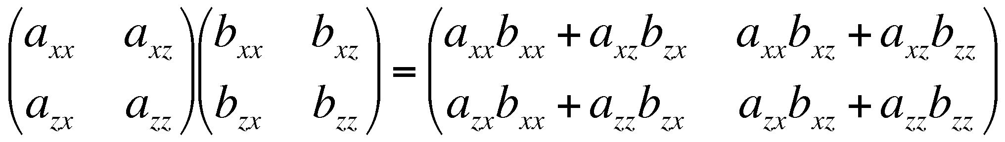
A vector is just a one-column matrix. If a vector is used to represent the coordinates of a point in space, then matrix multiplication may be used to transform that point to a new location.
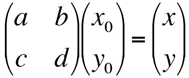
This can also be written Fx0 = x
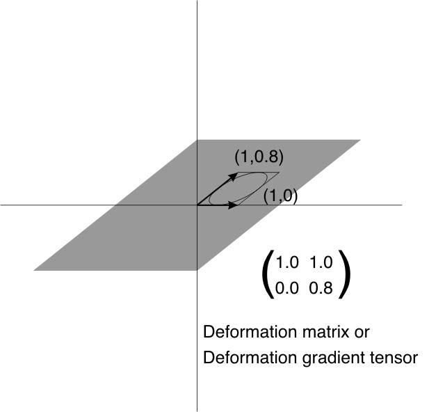
As an experiment, draw a simple diagram of a fossil on graph paper. Note the coordinates of selected points on the outline of the fossil, and transform them using the matrix:
![]()
What type of strain is the result?
![]() The matrix that does nothing
The matrix that does nothing
![]() A matrix that describes a simple dilation
A matrix that describes a simple dilation
A rotation clockwise about the origin ![]()
![]() A pure strain with strain axes parallel to x and y
A pure strain with strain axes parallel to x and y
A general pure strain ![]()
A simple shear parallel to x ![]()
For strain ellipse with principal stretches S1, S3. θ is initial clockwise angle of S1 from x axis; θ' is clockwise angle of S1 from x axis after deformation.
a = S3 sinθ' sinθ + S1 cosθ' cosθ
b = S3 sinθ' cosθ - S1 cosθ' sinθ
c = S3 cosθ' sinθ- S1 sinθ' cosθ
d = S3 cosθ' cosθ +S1 sinθ' sinθ
It's also possible to find features of the strain ellipse, given the deformation matrix. For example, using the same matrix

The dilation is given by
1+Δ = ad-bc
If you have worked with matrices before you may recognize ad-bc as the determinant of the matrix.
The rotational component of deformation is given by
tanω =(b-c)/(a+d)
The orientations of the strain axes are given by
-tan2θ'=2(ac+bd)/(a2+b2-c2-d2) where θd = angle of a strain axis clockwise from axis x after deformation.
The principal strains are given by the two solutions to the following
λ=0.5{a2+b2+c2+d2 + √[(a2+b2+c2+d2)2 - 4(ad-bc)2]}
Sometimes (especially when we deal with infinitesimal strain) we will have need of two other matrices.
The displacement gradient tensor J is related to the deformation matrix, very simply:
J = (F - δ) =![]()
When a point x is multiplied by J, the result is a vector describing the displacement of x (ie its change in location).
Jx0 = x - x0
A variant of the displacement gradient tensor is known as the strain tensor, which represents the non-rotational part of the deformation. Recall that a pure strain (no rotation of the strain axes) is represented by a symmetric matrix. We can design a symmetric matrix that comes close to representing the strain component of displacement, by averaging the two asymmetric terms b and c. This gives a matrix called the strain tensor E
![]()
F=
Calculate the reciprocal deformation matrix:
Actually, because only the distortion matters for rotation, it's possible to ignore the dilation. If we assume the dilation ab-cd = 1 then the simplified reciprocal matrix becomes 
Multiply each vector by this matrix to restore it to an original orientation.
Here are examples from the Meguma Group of NS showing the reorientation of paleocurrents