Material on this page is copyright © 2018 John W.F. Waldron
In this version, links that show as broken or unavailable refer to images and other material which is only available in the lectures and cannot be distributed on the web [generally for copyright reasons].
Belts of deformed sedimentary rock in which the layers are folded and duplicated by thrust faults are common at the external edges of orogens. Folds and reverse faults are the dominant structures in unmetamorphosed rocks exposed in a belt that may be tens or hundreds of kilometres wide.
Classic examples occur in:
"Foreland fold and thrust belts" typically involve shelf rocks or a former continental margin (or miogeocline).
They often also involve strata of the early part of the foreland basin that have later been incorporated into the orogen.
Some thrust belts (e.g. the Rockies) involve only the sedimentary cover, but many (e.g. Alps) involve basement metamorphic or igneous rocks, brought to the surface on steeper reverse faults.
In some fold and thrust belts there are sediments that were deposited in small basins on top of the moving thrust sheets: "Piggy-back basins". (None preserved in Rockies)
In many orogens sedimentation continues in some areas even after folding and thrusting began in others. Typically, an influx of immature clastic sediment accumulates ahead of the thrust sheets in a foreland basin.
In and adjacent to the external zones of many orogens are sedimentary basins with characteristic form.
The history of the foreland basin is best envisaged by imagining the orogen as fixed; the basin moves towards it. Any given point experiences:
The sediment fill may or may not fill the foreland basin to sea level.
Any low-angle reverse fault is called a thrust fault or simply a thrust. There is no formal definition of what constitutes 'low-angle', but most faults that are called thrusts have dip <45°
Because folding and thrusting are closely linked in most thrust belts, it's quite common for an originally low-angle fault to be rotated either
In either case, such faults are still called thrusts in most published descriptions, even though they would technically be classified otherwise. Notice that for the most part, such faults still cut bedding at low angles.
There is an alternative definition of thrust (that avoids these ambiguities): A thrust is a fault that puts older rocks on top of younger. This definition works well in areas that had undeformed stratigraphy in prior to shortening (like the Rockies), but breaks down if there are prexisting steep structures like folds or faults.
We can distinguish the hanging wall (above the fault plane) from the footwall (below).
Many thrust faults are non-planar. Most commonly, steeper and more gently dipping segments are present.
Typically, ramps and flats correlate with stratigraphy.
Regional flats are known as décollement surfaces. Several stratigraphic units in foothills are décollements.
Notice that although the thrust changes from ramp orientation to flat orientation, the overlying hanging wall strata are may be more or less parallel to the thrust. Hence we need definitions for ramps and flats that make clear whether we are talking about the hanging wall or the footwall. We distinguish
Pine Mountain thrust in the Appalachians shows examples of all four.
Ramps need not be oriented parallel to the overall strike of the orogen.
Lateral ramps can be quite steep. Direction of thrusting is typically parallel to the strike, so hangingwall block does not have to climb up the dip slope.
Where thrust faults cut stratigraphic boundaries there are cutoff points in cross-section. Typically, for a given stratigraphic horizon, we can identify a footwall cutoff point and a hanging wall cutoff point. The separation between them is evidence for the amount of displacement - though we need to know the slip direction to be precise about this.
In 3-D each cutoff point corresponds ot a cutoff line: the line of intersection between a bedding plane and a fault.
Sometimes thrusts lose displacement in the direction of transport. Typically this occurs when the hanging wall is folded or otherwise internally deformed but the footwall is not. Eventually, the offset may fall to zero.
Faults can die out laterally too, producing a lateral tip line where offset dies to zero. Typically another thrust takes up the offset as in the diagram.
In many thrust belts the folds are asymmetric (S-folds or Z folds), and also show vergence toward the foreland. In this case we recognize
Early descriptions of fold and thrust belts adopted a terminology in which thrust were described in relation to folds
This is a purely geometric classification. It suffers from the disadvantage that the classification of a given thrust depends on the erosion level. A backlimb thust might pass into an out-of-the-syncline or forelimb position as it is traced up or down-dip.
More recently another type of classification of folds in thrust belts has been developed, in which folds are related to thrusts (rather than the other way round). This classification is not purely geometrical; it has a relationship to thrust kinematics which we will explore more fully in the next section.
Folds are almost always associated with thrusts and we can recognize a number of different fold styles that are characteristic of thrust belts. Thrust belts almost always combine ductile strains with brittle faulting, and most analyses of thrust-related folding require some assumptions about the type of strain. Some common assumptions are:
In addition, many fold models assume:
We will meet these assumptions again when we consider section balancing later in this unit.
Because of these assumptions, it is easiest to construct diagrams of thrust-related folds using a kink-fold geometry. Kink folds are characterized by:
Note that although this construction is a matter of convenience, real folds do not necessarily (or even commonly) conform to this geometry. Nonetheless, a curved fold may often be approximated by a large number of kink-like hinges.
Fault bend folds are folds formed at bends in fault surfaces, typically changes from ramp to flat or vice versa. When movement occurs on a curved fault, rotation and/or distortion of the wall rocks must occur to preserve strain compatibility. Typically, for a large-scale fault with ramps and flats, the hangingwall is folded to accommodate to the shape of the footwall ramps.
The conspicuous fold in the hanging wall McConnel thrust at Mount Yamnuska is probably an example of a fault-bend fold.
Because ramps typically dip at < 40°, fault-bend folds are typically open folds.
If we assume that folds are angular (kink-style) and make some standard geometric and kinematic assumptions that require the fold to balance, it's possible to derive some simple trigonometrical relationships for the angles. The general relationship is complex:
but if we assume a simple geometry where one part of the fault is a true flat then the relationship is simpler
Detachment folds are folds formed above a flat or décollement surface, to accommodate a change in slip. Some examples are particularly conspicuous in cross-sections of the Jura Mountains, in the thrust belt of the Swiss Alps, where the underlying décollement is located in a layer of Triassic evaporites.
Fault propagation folds occur at ramps, as the tip of a fault climbs up a ramp during fault propagation. Strata at the base of the ramp are shortened by thrusting. Strata above the tip of the fault are shortened entirely by folding. In between, strata are shortened by a combination of folding and faulting.
Once again, it's possible to predict the inter-limb angle of a fault propagation fold based on the angle of the ramp, subject to general "balancing" assumptions and kink geometry.
It is possible for the fault tip to propagate beyond the area of folding, leaving the fold truncated in the hangingwall.
There may be a continuum of geometries between 'classic' detachment and 'classic' fault-propagation folds.
Thrusts do not occur alone. There are a many of characteristic geometries of multiple thrust faults. Because they are much studied in oil exploration, there is a great variety of terms surrounding thrust fault arrays.
In general, thrust faults that have en echelon arrangement in cross-section are described as imbricate.
A series of imbricate thrust faults that branch out of a single, deeper 'floor' thrust is known as an imbricate fan. [e.g. Taiwan thrust belt]
The points on a cross-section where the traces of two thrusts meet is called a branch point.
In 3-D each branch point corresponds to a branch line.
The branch points at the floor of an imbricate fan, where two thrusts branch when traced toward the foreland, are called trailing branch points.
Sometimes we can find other branch points where two thrusts join into one as they are traced toward the foreland. These are called leading branch points.
In 3-D we recognize leading and trailing branch lines.
Where a series of thrusts connects both with a floor thrust below and a roof thrust above, the configuration is known as a duplex. The individual thrust-bounded slices in a duplex are called horses.
Photo of outcrop-scale duplex at Crowsnest Pass
There are multiple trailing branch points at the floor of a duplex, at the hinterland end of each horse.
At the roof, thrusts join as they are traced toward the foreland; the foreland limit of each horse is marked by a leading branch point.
Some duplexes exhibit very regular geometry, but in others the amount of offset between horses varies greatly. In some cases the horses are piled on top of each other to form an antiformal stack. If the displacement is higher for higher horses, they may have moved right over the antiformal stack to produce a foreland dipping duplex.
In the above examples all the thrusts have the same sense of offset (e.g. west-over-east), but there are areas in thrust belts where thrusts of opposite sense - conjugate thrusts - are developed.
A tectonic wedge is a body of rock that has moved between a pair of oppositely vergent thrusts.
A triangle zone is a wedge in which a third, foreland-vergent thrust completes a triangle in cross section.There is a particularly prominent triangle zone at the eastern margin of the Alberta foothills. Cross section of triangle zone at Oldman River
Passive roof duplex - a duplex that fills a tectonic wedge. The prominent duplex of Belly River sandstone (yellow) has roof and floor thrusts with opposite vergence; the duplex has thickened the contents of the triangle zone while simply raising its roof.
Also, note that the passive roof duplex becomes very thin towards the eastern tip of the triangle zone. This type of thin passive-roof structure is sometimes called an intercutaneous wedge.
Several rules for thrust kinematics have been proposed, based on early experience with petroleum exploration particularly in the Cordilleran foothills. These rules are variously known as "Dahlstrom's rules" or "foothills rules". Although these rules are much quoted, many exceptions are known, so they must be used with caution.
There are many exceptions to rule 3. Thrusting that obeys rule 3 is knows as "in-sequence" thrusting. If a thrust develops above an already existing thrust it is an "out of sequence thrust"
Note: this section is mostly a recap of material covered in EAS 233 and many elementary courses on structure. We may skip this in the lectures if we are short of time.
Many methods of kinematic analysis require a cross-section parallel to transport. How do we find the transport direction?
This is the ideal. If there is a linear feature that pierces the thrust in both the hanging wall and the footwall then we can determine the displacement vector precisely. Suitable linear features include:
Slickenlines on fault surfaces and other features such as slickenlines, chatter marks and Riedel shears may also give a direction. Features of this type to show only part of the deformation history; if slip direction varied, they may be misleading.
In most thrust belts the majority of fold axes are perpendicular to the transport direction. The usual method is to plot poles to bedding on an equal area projection.
This method is subject to uncertainty if there are many lateral ramps or other oblique structures in the belt.
Thrusts cutting flat-lying stratigraphy always cut up section in the direction of transport. This is even true of oblique ramps.
Note: this section is mostly a recap of material covered in EAS 233 and many elementary courses on structure. We may skip this in the lectures if we are short of time.
If transport direction is known, other criteria can indicate the distance that a thrust sheet has moved.
The most reliable method is to match corresponding cutoff lines on ramps in the hanging wall and footwall.
It's sometimes also possible to match the ramps and flats themselves between hanging wall and footwall.
Sinuosities in the thrust front, together with fenster and klippen, may provide a minimum distance of thrust displacement
In many thrust belts, conventional cross-section construction cannot constrain the deep structure. For any set of field and well observations, there are many solutions to the subsurface structure. To supplement traditional methods, we use section balancing to constrain our models. This is a set of techniques designed to weed out "wrong" answers.
A balanced cross-section is actually a pair of cross-sections:
Section balancing is typically an iterative process, involving trial-and-error modification of both sections.
To balance a section, we need to be able to make the following assumptions:
The net effect of these assumptions is that each unit must have the same area in the present-day cross-section and in the restored section (area balancing).
In addition, we may make the following additional assumptions where warranted by the overall structural style:
Typically, a first attempt at a section will show some inconsistencies at step 4. These will be adjusted by repeating the whole process.
Line-length balancing is used when folds have parallel or kink style. Under these circumstances, layer thicknesses remain constant. Hence to maintain area, it is only necessary to maintain bed-length (because the area of a layer in cross-section is equal to thickness x bed-length).
In line length balancing it is useful to mark a vertical line in the unfaulted, autochthonous section, known as a pin-line. Bed-lengths can be measured with reference to this line.
It is sometimes useful to place a marker line perpendicular to bedding in thrust sheets too. Such a line is called a loose-line. Loose-lines are used to monitor the strain required in thrust sheets.
In general, for a section to be regarded as viable, loose-lines in long, tabular panels of strata should stay straight. If a loose-line has to be deformed, the sense of shear should be constant through the entire thrust unit.
If folds are not parallel or kink-style, and bed-thicknesses vary, then it is necessary to use area-balancing. This involves more tedious calculations and is less highly constraining on the final section. We measure the area of units on the deformed section, and draw equivalent areas on the restored section.
Some features to check
Note that the fact that a section balances doesn't mean it's right. There may be several viable solutions to the same data.
In particular, kink-style section constructions have become very popular because they are relatively easy to balance. Line-length balancing around folds works 'automatically' in such sections. However, this does not make these sections correct. Remember that any simplified geometry is likely to be no more than a convenient approximation to the truth!
The dynamics of thrust sheet motion is one of the has been a concern to structural geologists ever since major thrust sheets were first described in Europe in the 19th century. Examples in the Alps, Caledonides of Scotland showed distances of overthrusting of 10s of km. Some Scandinavian examples showed 100s of km, based on klippen and fenster, and yet thrust sheets are often only a kilometre or two thick.
It's not mechanically possible to push a sheet of these dimensions. In order for a sheet to move up an inclined surface, sufficient force has to be applied to overcome:
Both types of force can be calculated. In general it can be shown that if sufficient force is applied to the back of a block to overcome friction at the base, the block will fracture or crumple close to the place where the force is applied. Thus the emplacement of large thrust sheets appeared to pose a major mechanical paradox.
Numerous suggestions were made during the 20th century. Successive models have incorporated elements of previous hypotheses, with the result that it is now possible to predict many, though not all, features of observed thrust belts.
One explanation was that thrust sheets are not pushed but slide downhill under gravity following elevation of a mountain belt. Popular in the mid 20th century, this model has fallen from favour. It was discovered that high-grade rocks in the cores of orogens are not older, uplifted basement, but instead are metamorphic equivalents of the same units in the thrust belts. Hence there is no obvious source for large gravity slides.
However, the role of gravity has incorporated in more recent models for thrusting driven by shortening.
Hubbert and Ruby observed that high fluid pressure could partially support the weight of thrust sheets. (See the description of the 'famous beer can experiment' in the text by Davis and Reynolds.) Frictional resistance is proportional to the normal stress on a surface, so reducing normal stress reduces frictional resistance.
In an extreme case where water is unable to escape from the basal region, the weight of the thrust sheet would be entirely supported on fluid, reducing the frictional resistance to near zero.
A large elevated body of rock produces a higher pressure beneath its base than in surrounding areas. This elevated pressure may be sufficient to overcome resistance to sliding or other types of deformation, allowing the elevated region to spread, with a wedge-shaped cross-section. Although rock moves uphill on the basal boundary of the wedge, the overall centre of gravity falls, as body thins. Hence no external force has to be applied to overcome gravity.
Chapple, and subsequently Dahlen and co-workers, realised that most thrust sheets are part of a wedge shaped stack.
Their model builds on the earlier gravity spreading model. They allow the base of the wedge to be weak, because of fluid pressure. Internally, they assumed that the material of the wedge follows the Mohr-Coulomb failure criterion, faulting as necessary to prevent shear stress rising above the failure envelope. Rocks effectively increase in strength as lithostatic pressure rises; hence the back end of the wedge is effectively stronger than the front.
For a given set of boundary conditions - slope of basal décollement, strength of basal layer, strength of wedge - there is critical angle between the top of the wedge and its base, known as the critical taper.
The equation relating all the various quantities is quite complex
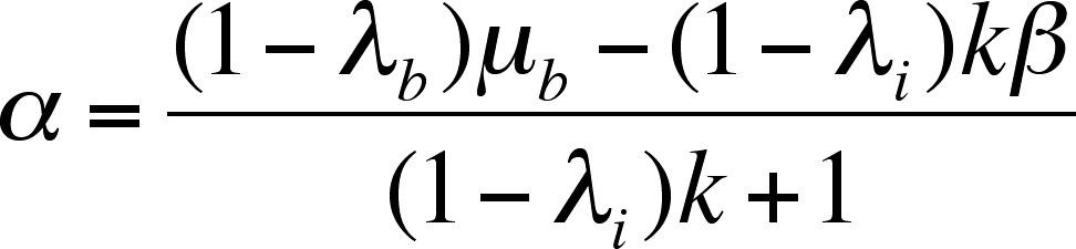
where
surface slope is α
and décollement slope is β
The internal strength (yield stress) of wedge is k
Internal fluid pressure ratio is λi
Décollement fluid pressure ratio λb
Décollement friction μb
When the wedge is at critical taper, and is moving, it is at the point of failure throughout. The assumption of Coulomb failure is equivalent to assuming that the material is plastic, with a depth-dependent yield stress. However, subsequent variants of wedge models have become quite diversified and have incorporated a number of different types of rheology.
The general principles of wedge models have been tested by